Table of Contents
Hardware
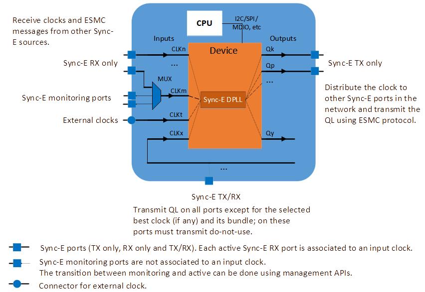 Figure 1. Hardware inter-connection between SyncE ports, external clocks, inputs, outputs, the DPLL device, and the CPU running
 synced application.One or more external multiplexers can be used to connect multiple SyncE ports to a clock.
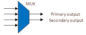
The multiplexers can be both single-output or dual-output:
Those ports connected to external multiplexers, which are not associated to a clock, are called SyncE monitoring ports. The transition of a SyncE port from monitoring state to active state can be done automatically using the event callback functions and the management APIs, or can be initiated by the user.
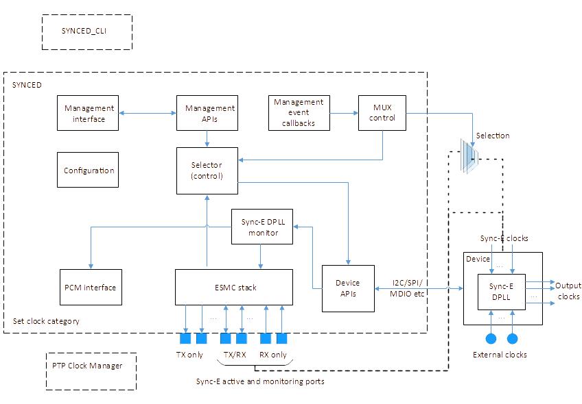 Figure 2. Software block diagram and the connection with the DPLL device..
Software
synced application runs on CPU and interacts with the DPLL device as follows:
- Read the DPLL status (Locked, Holdover, etc.).
- Read the selected clock index to determine the current QL.
- Read the device reference monitors status to notify the user when the physical clocks qualification fails.
- Set the selected clock, or write a clock priority table into the DPLL device.
Device APIs module implements the hardware abstraction layer.
The architecture is modular, and each software module performs simple tasks:
- The ESMC stack notifies the Selector when a SyncE port Quality Level has changed.
- The Selector sets the clock priority table into the DPLL device.
- SyncE DPLL monitor reads the DPLL and clock status and sets the current QL into the ESMC stack.
- PCM interface enables the communication with an external PTP Clock Manager application if needed. The purpose of this interface is to provide the current clock category.
- The management interface enables the communication with an external CLI client
SYNCED_CLI which is included in the open-source code. SYNCED_CLI implements all management APIs.
Configuration
The configuration file has two sections:
Global:
- ESMC network option
- No QL mode enable
- SyncE port forced QL enable
- LO QL
- LO Priority
- Device config file name
- SyncE DPLL index
- Holdover QL
- Holdover timer in seconds
- Hold-off timer in milliseconds
- Wait-to-restore timer in seconds
- PCM interface enable, IP address and port number
- Management interface enable, IP address and port number
- Syslog enable (configurable message level)
- Stdout enable (configurable message level)
Per port:
- [name] (ex: [eth0])
- Clock index
- Priority
- TX enable
- RX enable
- TX bundle number
- Initial QL
| Port type | [name] | Clock index | Priority | TX enable | RX enable | TX bundle number | Initial QL |
|---|
| Active SyncE clock | m | m | m | opt | 1 | opt | opt/n |
| External clock | m | m | m | n | n | N | opt/n |
| SyncE monitoring | m | n | m | opt | 1 | opt | opt/n |
| TX only | m | n | n | m | n | opt | n |
m = mandatory, n = must not be defined, opt = optional, default value applies if missing, 1 = must be set to 1
Management API
synced provides a set of management APIs to get information and set parameters. These APIs can be either called directly if the source code is integrated in other projects, or they can be called by other applications via Management Interface. This interface can be enabled and configured in the configuration file.
The APIs return one of the following response codes:
| Response code | Response | Details |
|---|
| 0 | Ok | The command finished successfully. |
| 1 | Invalid | One or more input arguments are invalid. |
| 2 | Failed | Command failed. Ex: port name cannot be found. |
| 3 | Not Supported | The command is not supported in current operation mode. |
Get a list of sync information structures, one for each port:
- Port name
- Port sync type (Active SyncE, External, Monitoring or TX only)
- Type-specific information:
| Information | Active SyncE | External | Monitoring | TX only |
|---|
| priority | x | x | x | |
| current QL | x | x | x | |
| sync state | x | x | x | |
| TX bundle number | x | | x | x |
| clock index | x | x | | |
| hoff/wtr remaining time [ms] | x | | x | |
| number of hops | x | | x | |
| rank | x | x | x | |
| sync clock state | x | x | | |
| clock reference monitor status | x | x | | |
| RX timeout flag | x | | x | |
| port link-down flag | x | | x | x |
Get a sync information structure for a specific port. The application provides the information for the specified port name.
Get current status:
- Current QL
- Selected port name
- Selected clock index
- SyncE DPLL state
- Holdover remaining time in milliseconds
Set forced QL per port
Clear forced QL per port
Clear holdover timer
Clear SyncE clock wait-to-restore timer per port
Assign a new SyncE port to a clock index
Set priority per port
Event Callback Functions
The purpose of the callback functions is to notify the user when an event occurs. The implementation is on user side; however, synced contains template code for each callback and examples on how to control the external multiplexers.
- Current QL
- Sync port current QL
- SyncE DPLL current state (Locked, Holdover, etc)
- Sync port current clock state (Qualified, Unqualified)
- Sync port current state (Normal, Forced, Wait-to-restore, Hold-off)
- Alarms:
- Timing loop detected
- Invalid QL received at port
- PCM interface status
Acronyms
| Acronym | Definition |
|---|
| DPLL | Digital Phase Lock Loop |
| DNU | Do-not-use |
| ESMC | Ethernet Synchronization Messaging Channel |
| ITU-T | International Telecommunication Union – Telecommunication Standardization Sector |
| LO | Local Oscillator |
| MUX | Multiplexer |
| PCM | PTP Clock Manager |
| PTP | Precision Time Protocol |
| PTP4L | Precision Time Protocol for Linux |
| QL | Quality Level |
| TLV | Type-Length-Value |